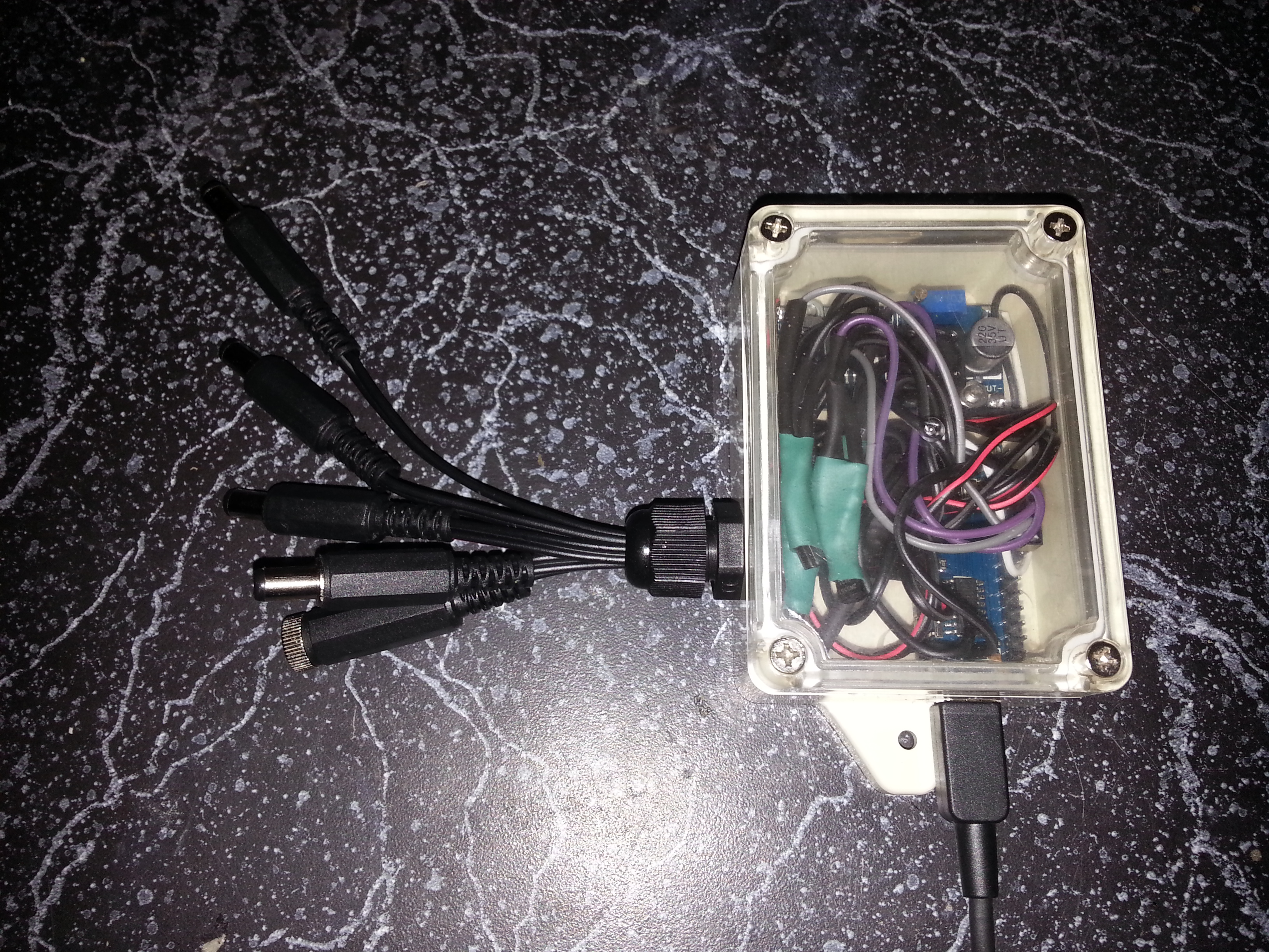
Summary
Make hydroponics pumps with timers (can be set to arbitrary time on/off).
Parts
To do this, you will need:
- Arduino (I used a nano)
- Buck converter (got one for about $1 on Aliexpress)
- Small project box
- 12V pumps (I got some for around $5 on Ali)
- Diodes (I'm using 1N4007)
- female and male DC jacks (5.1 x 2.1mm)
- Transistors (I'm using 2N5551)
- 39 Ohm and 390 Ohm resistors
- Some female-female jumper cables
- M2x16mm bolts
- M3x12mm bolts and nuts
- Various sizes of heatshrink
- 12V USB power adapter (account for about 0.5A for the Nano and 0.5A for each pump)
Creating the device
Enclosure
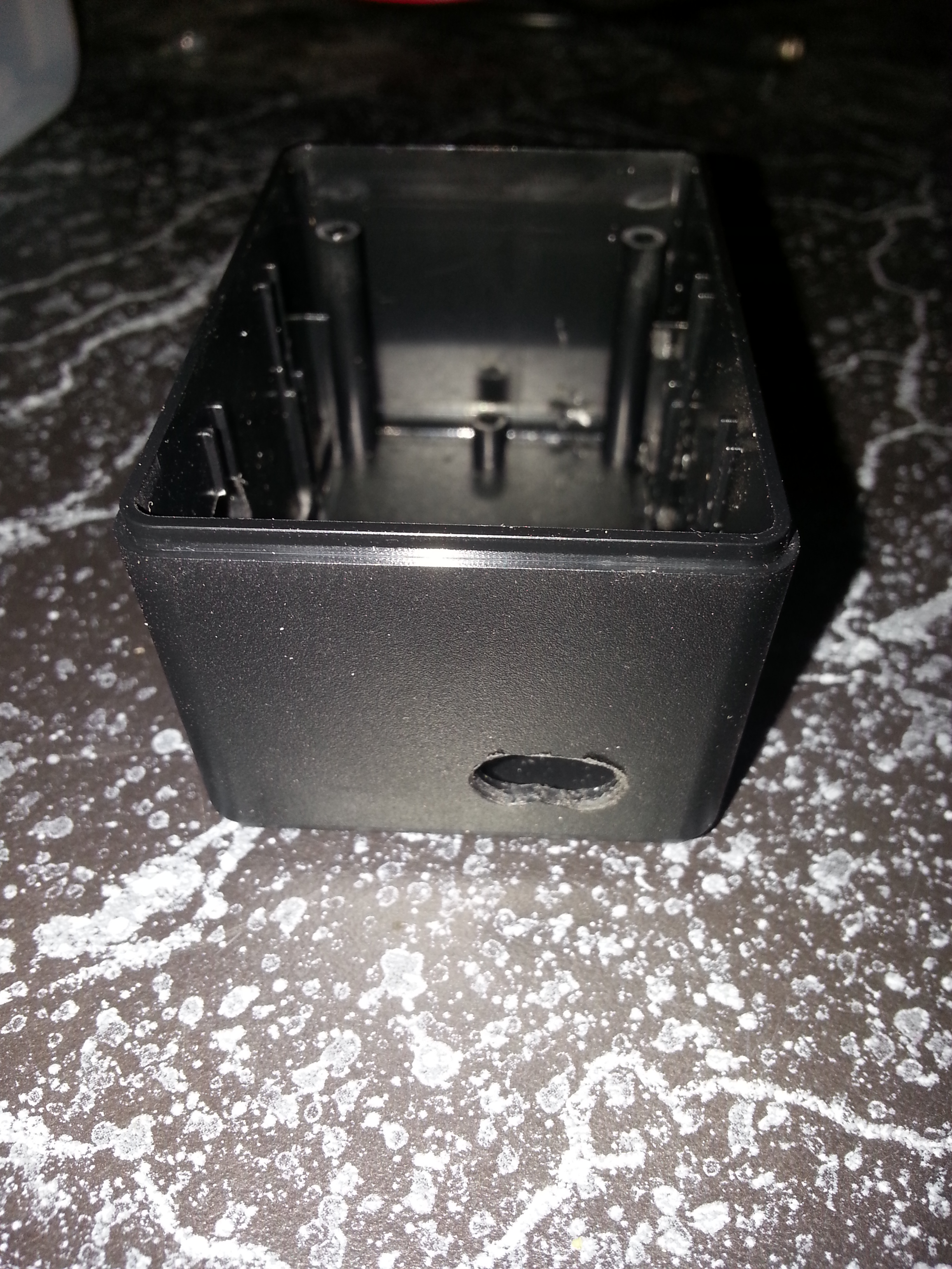
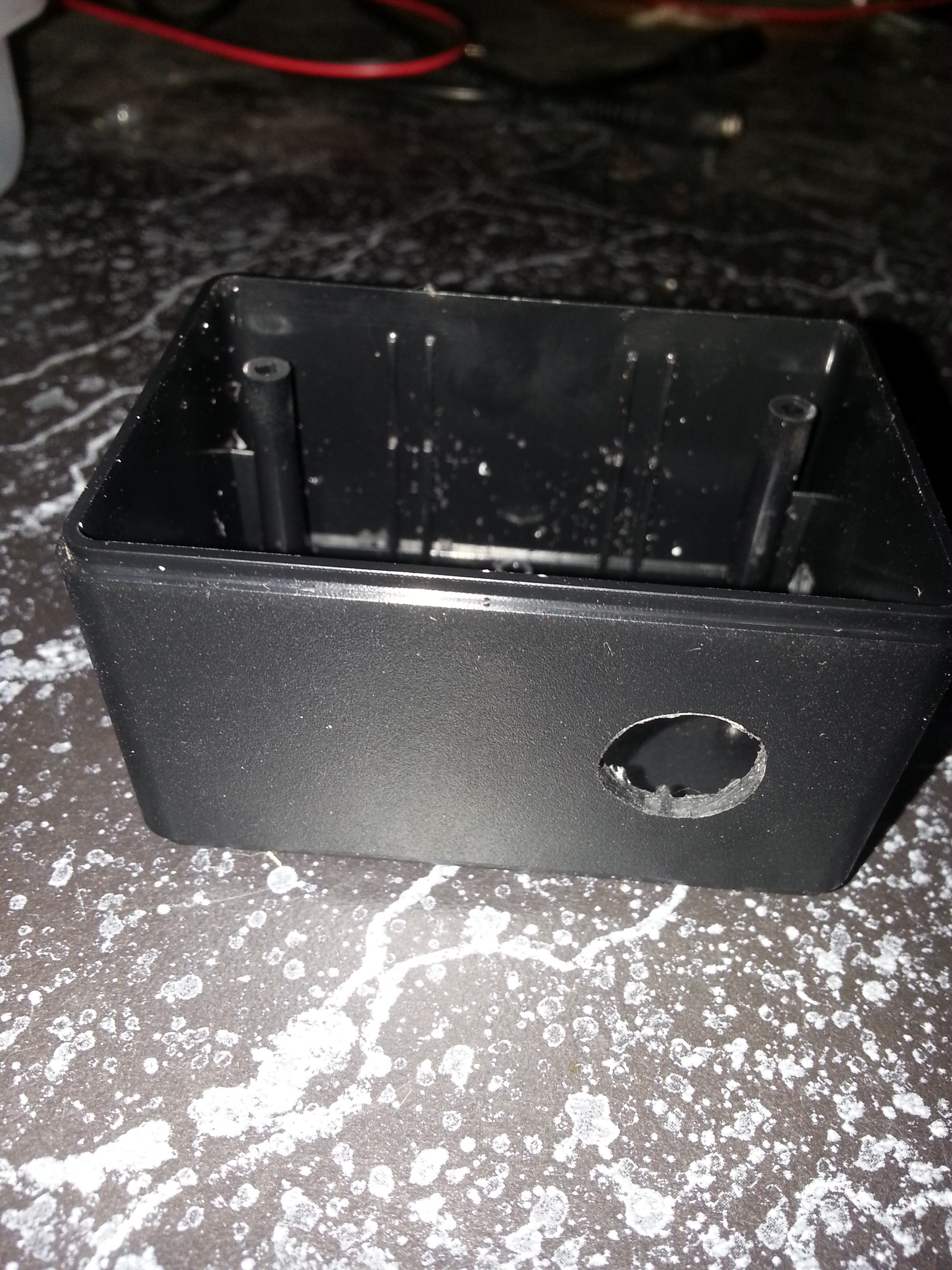
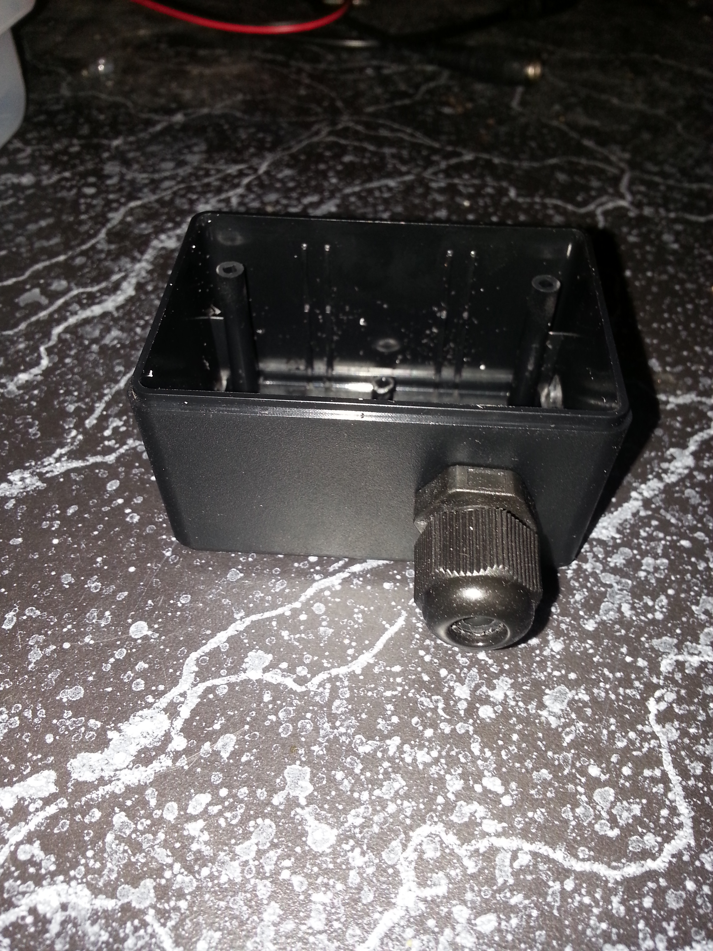
Drill holes in the box. I drilled 2 1/4” holes (you could use probably a 1/8” bit if the holes are very precise) for the USB plug for the Arduino Nano, and one 1/2” hole (with a spade bit). Then, install the PG-7 cable gland in the 1/2” hole.
Buck converter
In fact, this step is not necessary unless you are using a board that cannot accept 12V as an input. Arduino Nanos can accept up to 20V as an input (7-12V recommended), so the buck isn’t necessary for this. But for MCUs like the NodeMCU or Particle Photon (which can only take 5V max in), the Buck is necessary. Also, Bucks are typically 80-90%+ efficient, meaning you will use less power at 5V than at 12V for your Arduino.
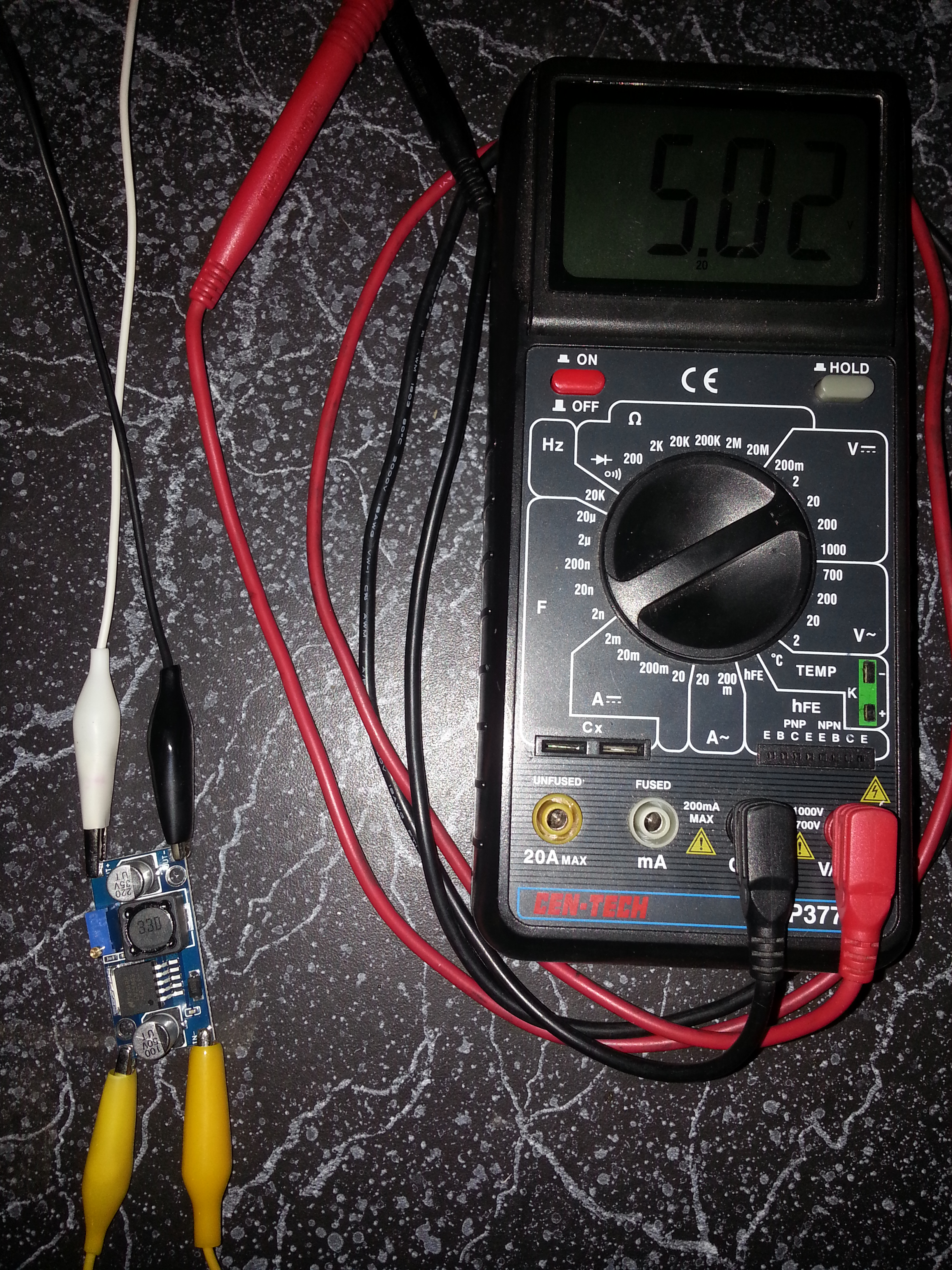
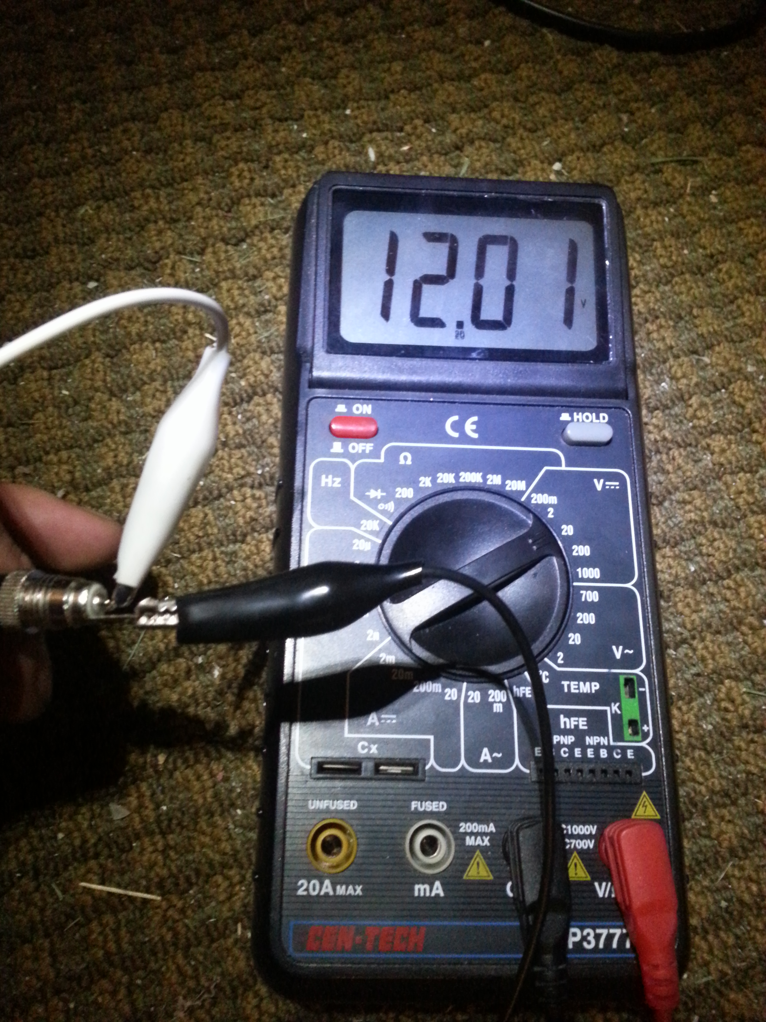
Use a multimeter and tune the buck converter so it outputs 5V from a 12V input. This way you will be sure the Buck will work before you install it.
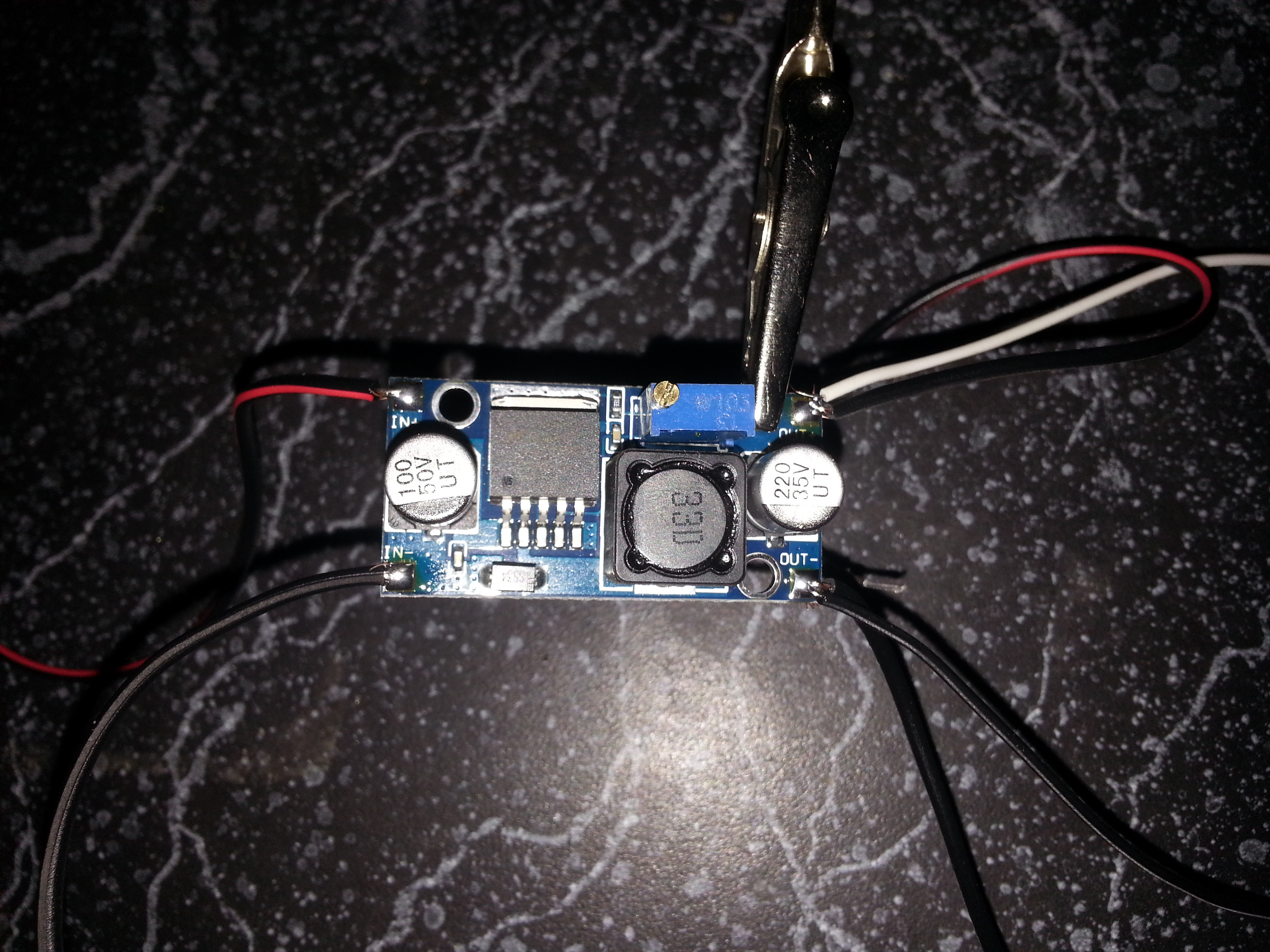
Solder female jumpers to the output of the Buck converter. Solder two sets of black and red wires to the input of the Buck converter. The female jumpers go to power the Arduino, the input wires are for 12V input power and power to the pump(s)
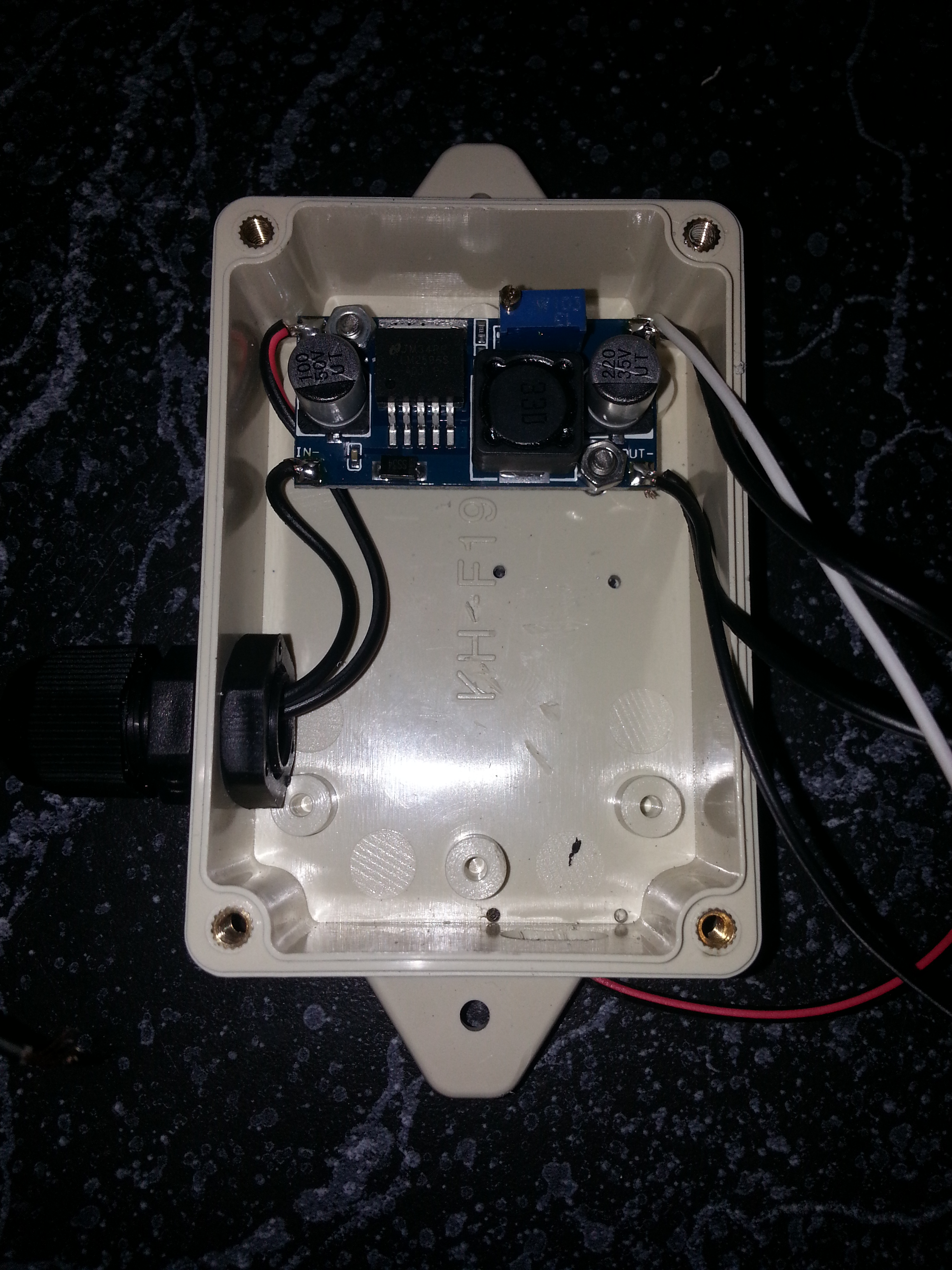
Now pass the black and red wires going to the Buck input through the cable gland, and solder on a female DC jack. Drill holes (~1/8”) using the Buck holes as guides. Affix the Buck with 2 3x12mm nuts and bolts.
Install Arduino
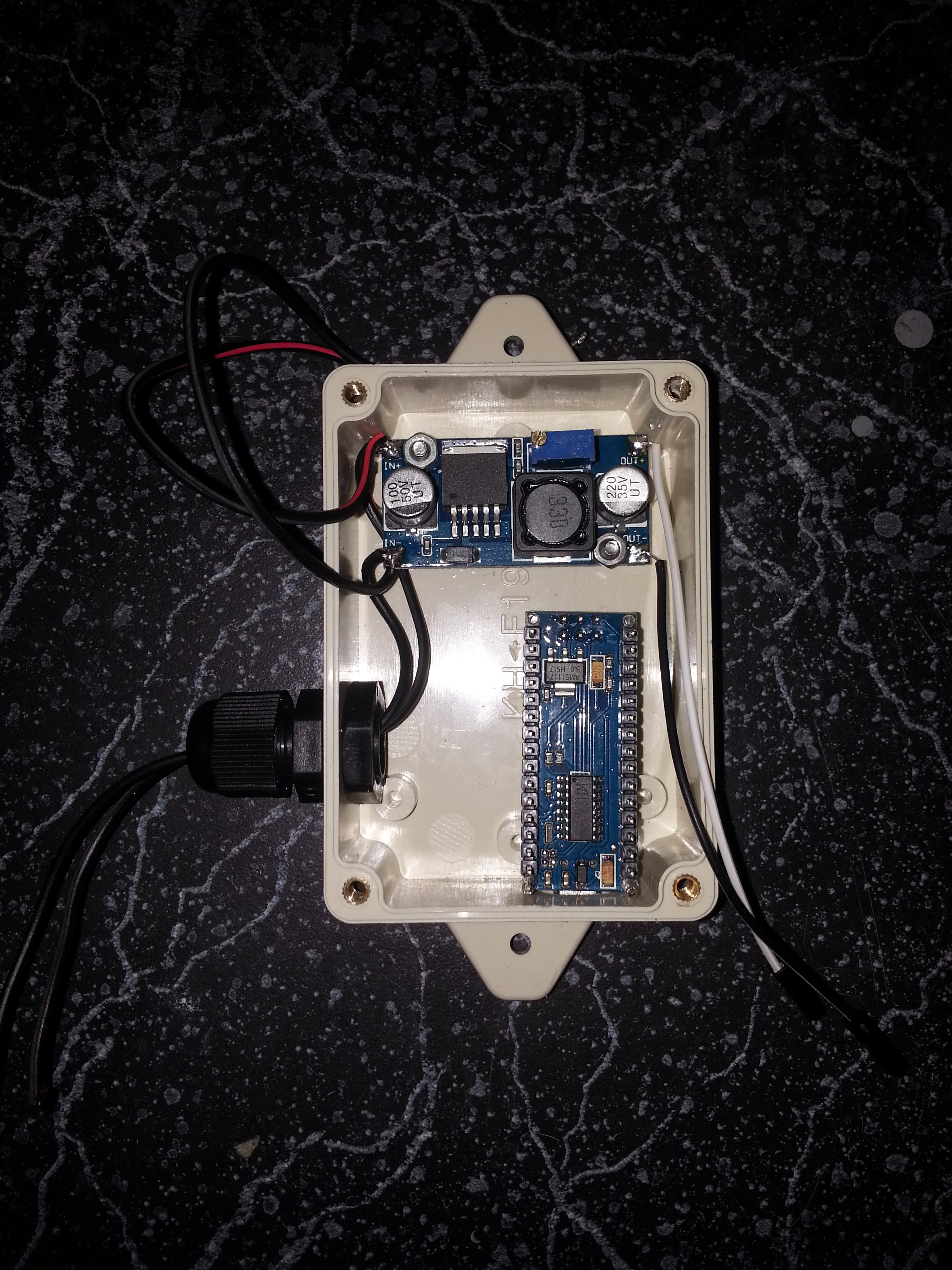
Put the Arduino in the case where it will go, and use the holes as templates for drilling (~1/16”) holes in the case. Then open the holes with a 5/64” bit. Affix the Arduino with M2x16mm nuts (and optionally bolts–I found the nuts screw firmly into the Arduino holes).
Preparing the Pumps
You need to solder some DC jacks to the pump wires, and a diode. The DC jacks usually have the outer part as negative, and the inner part as positive. This makes sense for safety, because it’s much easier to touch the outside of a DC jack than the inside.
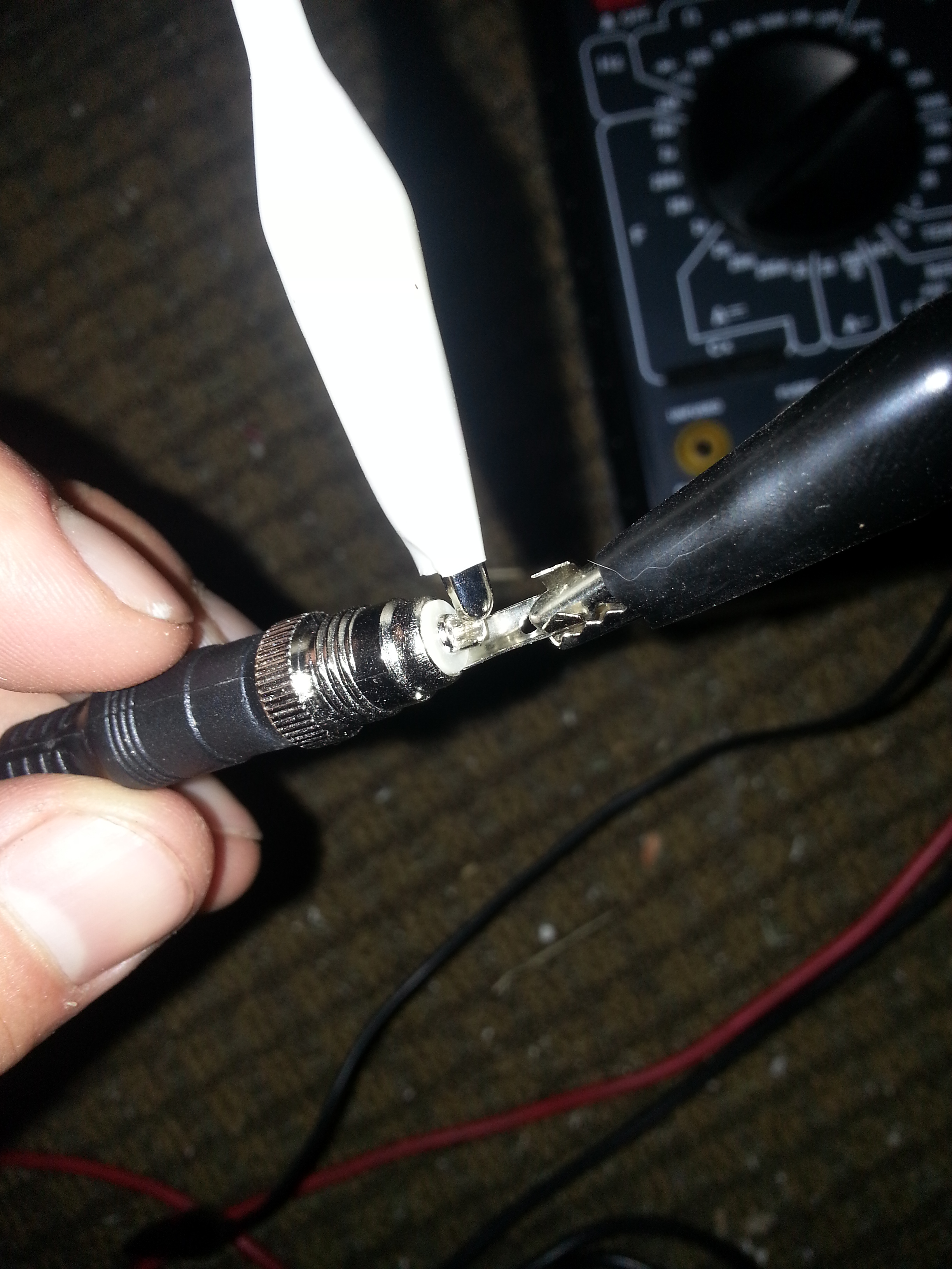
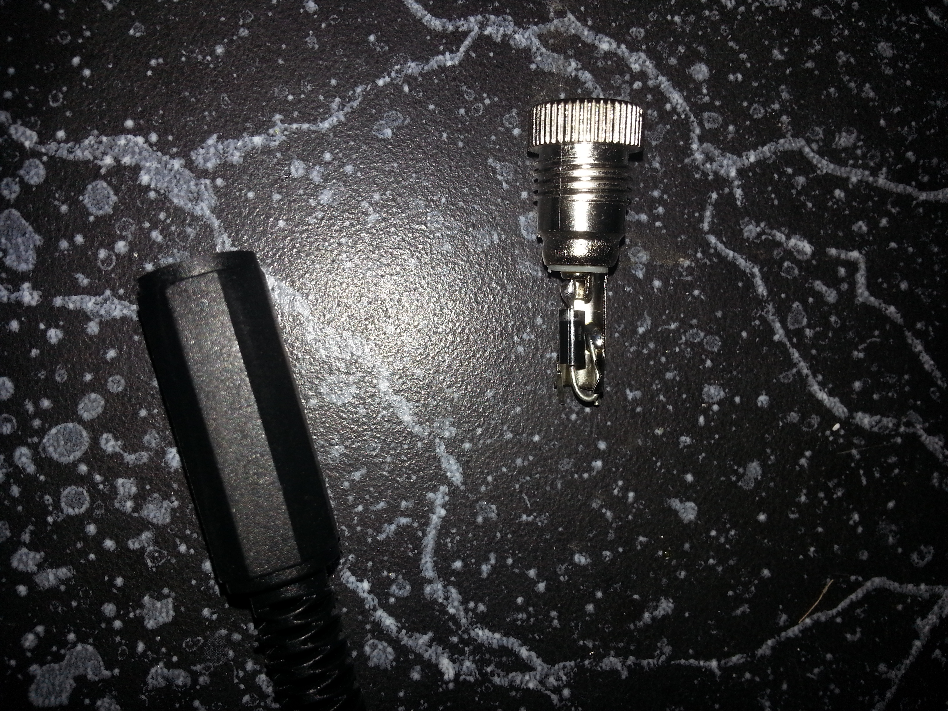
Solder a diode from the outside (negative) to the inside (positive) of the female DC jack for the pump. The white band on the diode should be pointing to the positive terminal on the DC jack. This will dissipate any current that flows in reverse when the power is suddenly shut off to the pump.
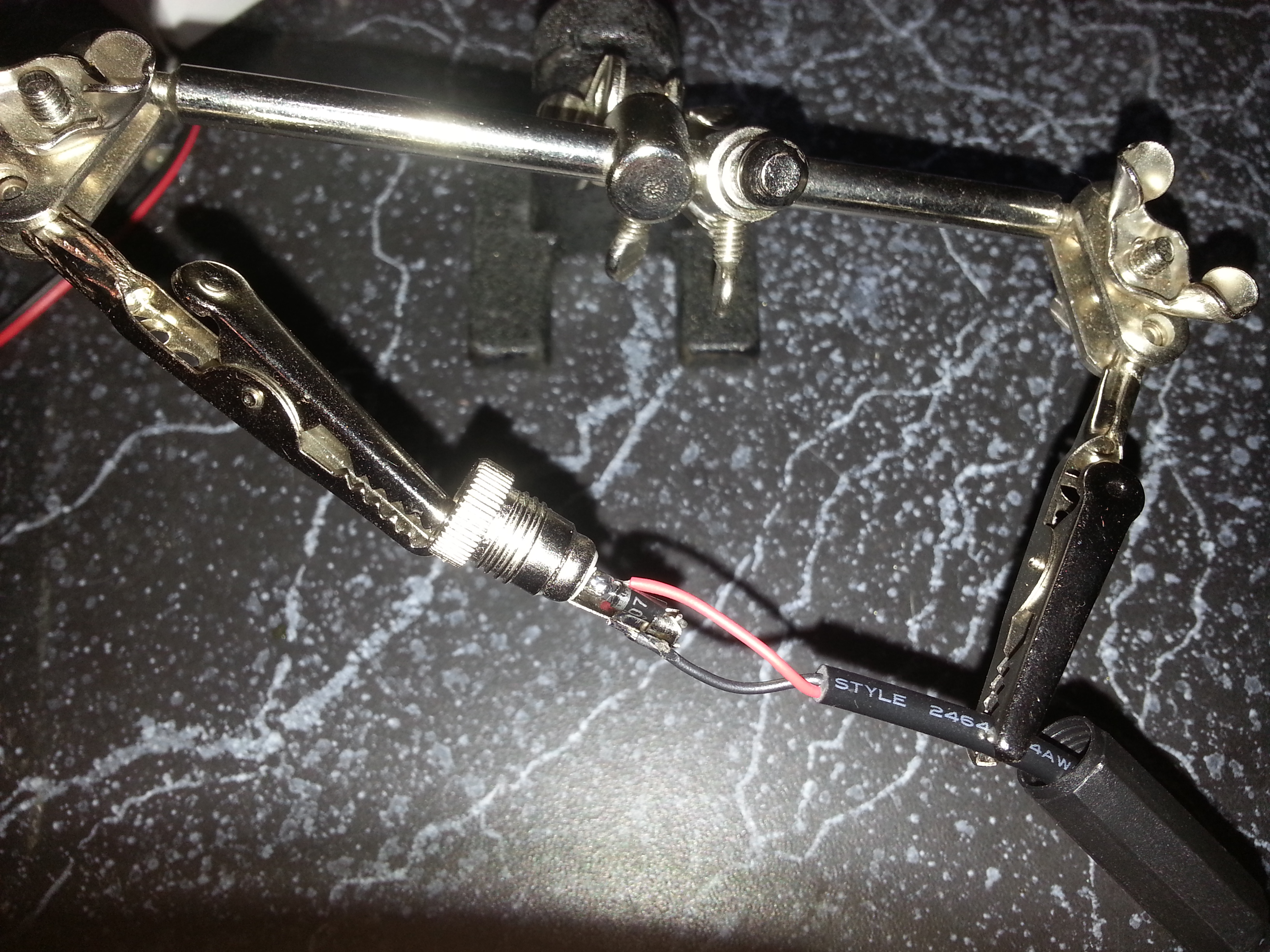
Before you do this next step, make sure you have the wires already passed through the DC jack cover so you can slide it over the jack when you finish soldering. Solder the red wire from the pump to the inside of the jack, and the black wire to the outside.
Transistors
The 2N5551 transistor is NPN, meaning we need to put a positive bias on the Base (relative to the Emitter) to turn on the pathway from the collector to the Emitter.
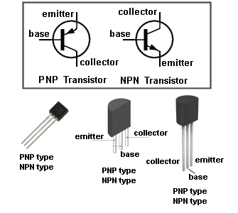
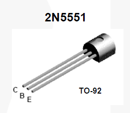
The exact amount of resistance needed depends on the input voltage to the Base, the transistor itself, and the current used by the pump. Solder a 33 Ohm resistor from the left to the middle of the transistor (Emitter to Base). This will make sure the transistor is normally off.
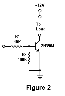
Solder a 330 Ohm resistor from the center leg (Base) to a female jumper. This will go to the Arduino for control.
Finally, solder the rightmost leg to a black wire, which will connect to the outside of a DC barrel jack for connecting to a pump.
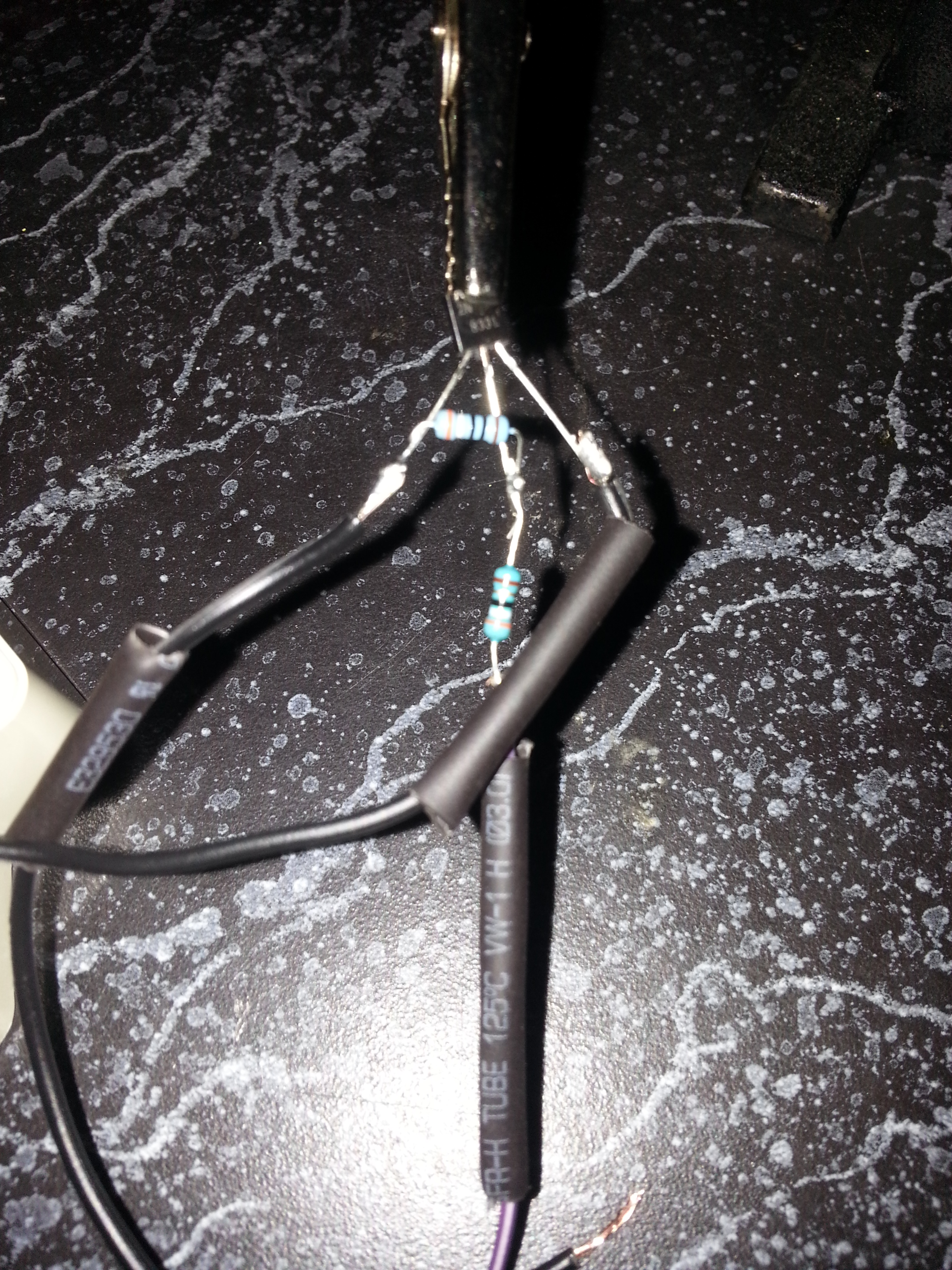
I then put some bigger heatshrink around the top of the transistors, to protect any exposed metal from accidental connections.
DC Jacks to the Pumps
Solder the black wire from the transistor Collector leg to the outside terminal of a male DC barrel jack for the pump. Solder a red wire to the inner terminal of the male DC jack, and the other end to the positive input from the buck converter.
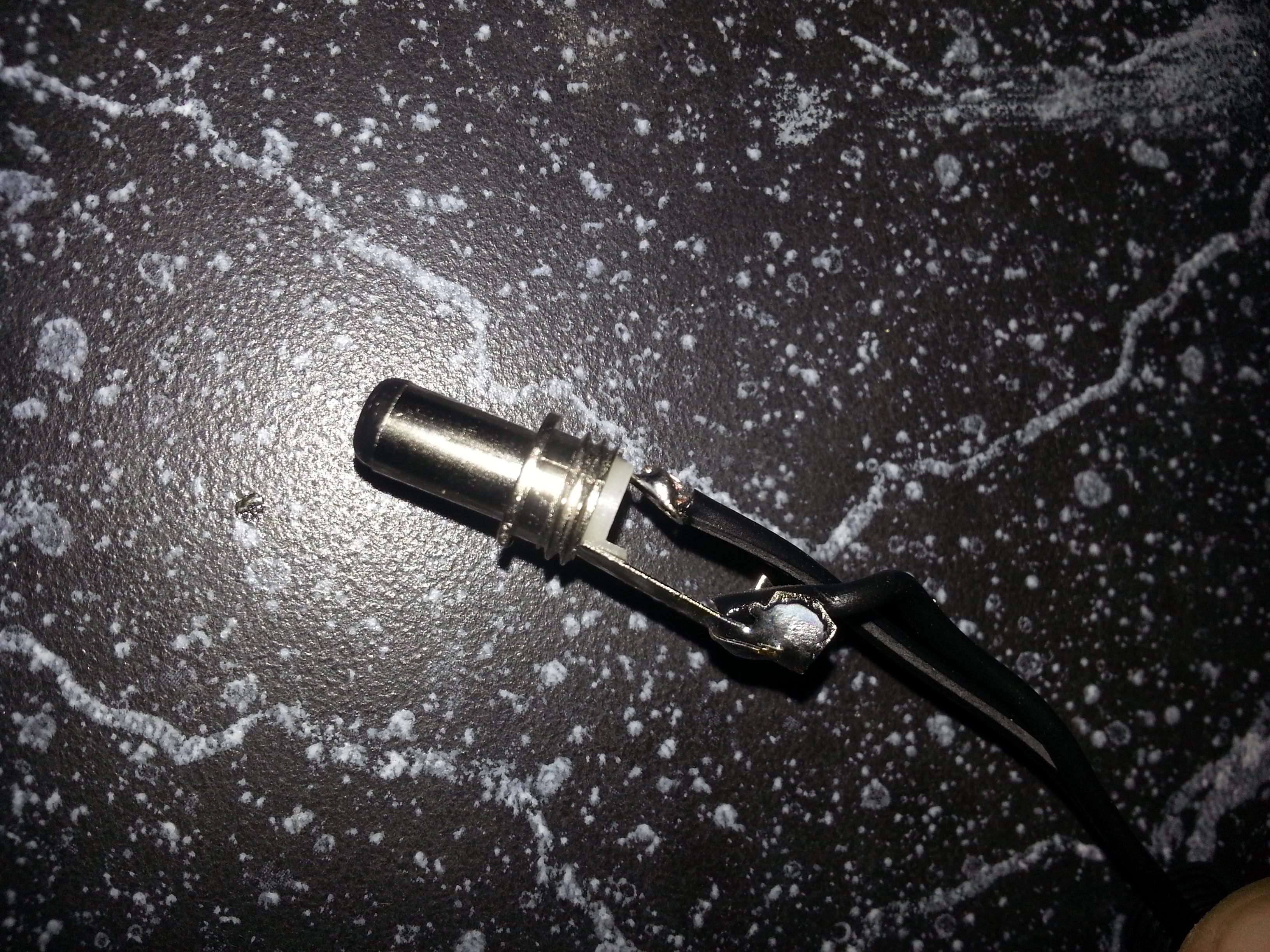
Solder the red wire from this DC jack to the red input power wire (coming from the Buck converter), and cover with in heatshrink.
Program the Arduino
I installed multiple pumps and transistors, and so checked which one was which by plugging in the female jumpers to the 5V pin on the nano and finding which DC jack it triggered. I then arranged the DC jacks from short to long, connecting the shortest DC jack to the D2 pin on the Nano, next shortest to D3, etc.

char* names[] = {"mini Tomato", "blueberry"};
int pins[] = {2, 3};
unsigned long timeOn[] = {20000, 0}; // time that the pump stays on for each 10000 = 10s pin in order

unsigned long timeOff[] = {3600000, 0}; // time pump stays off -- 3600000 = 1 hr

unsigned long startTime[] = {0, 0}; // time pump was turned on, in ms

bool pumpOn[] = {true, false};
bool disable[] = {false, true};

int pumps = sizeof(pins)/sizeof(int);

void setup() {
  Serial.begin(9600);
  Serial.println(pumps);
  initializePumps();
  //testPumps();

  digitalWrite(pins[0], 1);
  Serial.println("pump on");
  startTime[0] = millis();
  pumpOn[0] = true;
}

void loop() {
  for (int i = 0; i<pumps; i++) {
    if (disable[i]) {continue;};
    if (pumpOn[i])
    {
      if (millis() - startTime[i] > timeOn[i])
      {
        Serial.println("pump off");
        digitalWrite(pins[i], 0);
        startTime[i] = millis();
        pumpOn[i] = false;
      }
    }
    else if (not pumpOn[i])
    {
      if (millis() - startTime[i] > timeOff[i])
      {
        digitalWrite(pins[i], 1);
        Serial.println("pump on");
        startTime[i] = millis();
        pumpOn[i] = true;
      }
    }
  }
}

void testPumps() {
    for (int i = 0; i<pumps; i++) {
    Serial.print("testing: ");
    Serial.println(names[i]);
    digitalWrite(pins[i], 1);
    delay(1000);
    digitalWrite(pins[i], 0);
    delay(1000);
  }
}

void initializePumps() {
  for (int i = 0; i<pumps; i++) {
    pinMode(pins[i], OUTPUT); // make sure out pin is set to 'off'

    //i.e. pulls pin to ground

  }
}
The testPumps() function will go through each of the pumps and turn it on for a second, printing the name of the assigned pin in the terminal. Press ctrl+shift+M to access the terminal from the Arduino IDE (or Tools->Serial Monitor).
